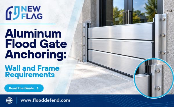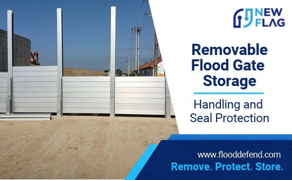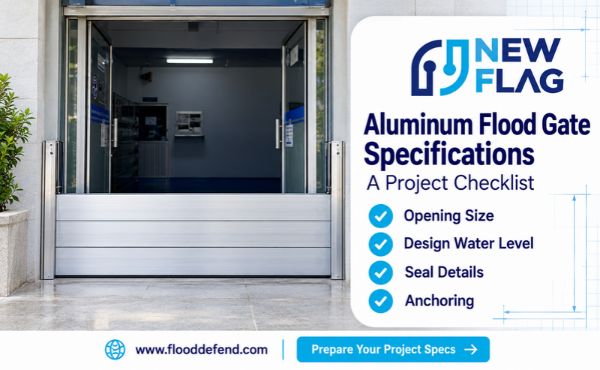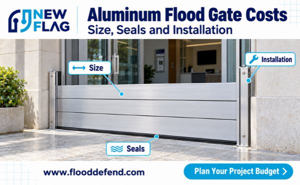
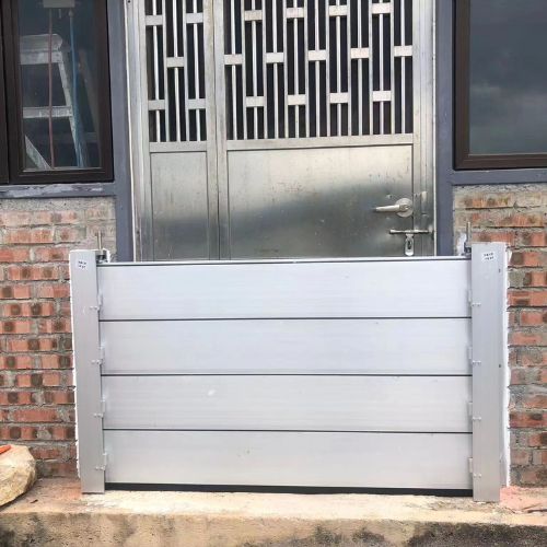
Aluminum flood gate anchoring must transfer the gate’s water loads into suitable building structure. The visible doorway trim, a thin cladding panel, or an ordinary decorative frame cannot be assumed to provide that support. A complete fixing design considers the gate reactions, substrate, anchor arrangement, frame stiffness, and connection to the rest of the building.
For project buyers and installers, the key distinction is between a surface that looks suitable for mounting and a structure capable of carrying the imposed load. Accurate dimensions establish where a frame can fit; they do not establish whether its fixings can resist flooding.
Water Loads and the Structural Path
Water pressure acts on the gate face and is carried through the panel into its supports. Depending on the system, those supports may include side frames, center posts, a sill connection, or braces. The fixings then transfer reactions into the wall or floor.
For still water with a dry protected side, pressure increases with depth. Increasing the design water depth therefore changes the loading significantly. A gate designed for a shallow event should not be made taller or used at a higher depth without reassessing the assembly and its supports.
The load path must remain continuous. Strong anchors do not compensate for a weak frame, and a strong frame does not compensate for unsound masonry. The building element receiving the load must also transfer it onward through its own connections.
The gate designer should provide support reactions for the approved configuration. The anchorage designer then assesses those reactions against the actual structure and applicable design requirements. Guessing anchor sizes from panel weight overlooks the much more important water loading.
Moving water, impact, or other site exposures may introduce additional demands. Specify which conditions the anchoring design includes rather than assuming a static-water calculation covers them automatically.
Substrate Identification and Condition
Identify the material behind the proposed fixing area. Reinforced concrete, solid brick, hollow masonry, structural steel, timber, and decorative finishes have different anchoring characteristics. “Wall” is not a sufficient substrate description.
For masonry, record the unit type, condition, thickness, and whether cavities are filled. An anchor suitable for solid concrete is not automatically suitable for a hollow block or a mortar joint. Manufacturer approvals and design data need to match the actual material and installation orientation.
Check for cracks, loose finishes, deterioration, and prior repairs. A fixing drilled through render must engage the approved structural substrate; the render thickness is not part of the effective embedment into that substrate.
Where records are incomplete, the responsible designer may require investigation, testing, or exposure of concealed construction. Testing should follow an appropriate plan and be interpreted for the project. A single informal pull on a bolt does not establish the capacity of the complete anchorage.
Also check the floor where removable center posts or braces connect. Thin screed, paving, or a decorative sill may conceal a suitable foundation, or may conceal none. Identify the supporting construction rather than inferring it from the finished surface.
Decorative Frames and Structural Support Frames
Existing door frames serve several functions, including supporting door leaves and retaining finishes. They were not necessarily designed for flood barrier reactions. Aluminum cover sections and glazing beads may be especially unsuitable as primary support members.
A mounting frame can sometimes connect through the existing finish to structural backing, provided that connection is designed. The load-bearing detail may include brackets, spacers, or a dedicated support frame. Such components must be assessed for their forces and geometry.
Spacers deserve particular attention. Increasing the distance between the flood frame and its structural support can change the bending demand in the fixings and brackets. A long bolt through a thick decorative build-up is not equivalent to a closely supported connection.
Where a new structural frame is needed, coordinate it with the gate supplier. Its stiffness and alignment affect both load transfer and seal contact. A frame that is strong but moves excessively may compromise the water-resistant assembly.
Keep glazing out of the assumed support path unless the design specifically includes it. Flood barriers mounted near glass entrances need a clear detail showing which structural elements receive the reactions.
Anchor Selection and Installation Parameters
Select anchors using the approved load design and the anchor manufacturer’s data for the actual substrate. Diameter is only one parameter. Embedment, spacing, edge distance, base material thickness, corrosion exposure, and installation conditions also matter.
| Design input | Why it matters |
|---|---|
| Support reactions | Establish tension, shear, and other connection demands |
| Substrate and condition | Determine which fixing data apply |
| Edge distance and spacing | Affect possible failure modes and group behavior |
| Effective embedment | Defines engagement in the approved base material |
| Frame stand-off | Influences connection geometry and bending |
| Exposure conditions | Inform material protection and durability |
Avoid a universal instruction such as “use four expansion bolts.” The required number and type depend on the frame layout, load, and structure. Adding extra holes without design review can reduce edge distances or damage a narrow masonry pier.
Installation requirements are product-specific. Hole diameter, drilling method, cleaning, setting torque, and any adhesive curing conditions must follow the selected fixing system’s instructions. Substituting a different anchor requires reassessment, not merely matching its nominal size.
Scan or investigate concealed services and reinforcement as appropriate before drilling. If a planned hole conflicts with reinforcement or a service, obtain a revised fixing detail. Moving the hole arbitrarily can invalidate the connection layout.
Frame Sealing and Alignment
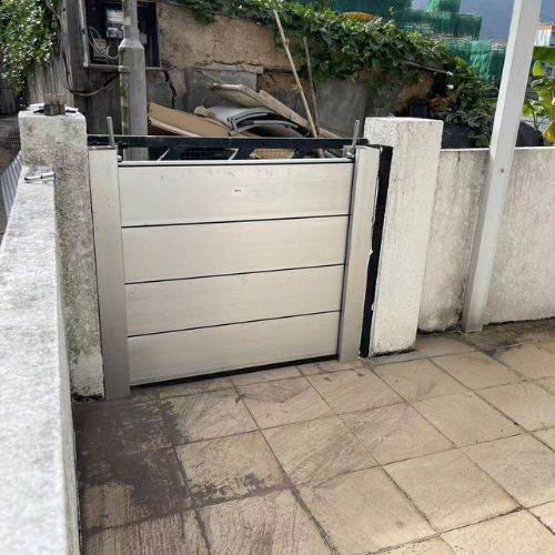
Anchoring and sealing are separate but connected tasks. Fixings hold the frame in position; the frame-to-building detail prevents water bypassing it. A mechanically secure frame can still leak behind its mounting face.
Specify the approved bedding, sealant, or other interface detail. Include substrate preparation and the treatment of joints at the floor. The interface must connect with the bottom sealing arrangement rather than leaving an unsealed corner.
Check frame alignment during installation. Tightening an unevenly supported frame can distort its seal contact face. Use the designed supporting and leveling method instead of pulling a bent frame straight with anchor torque.
Do not use soft, unapproved packing to fill structural gaps. It may deform under load or allow the frame to shift. Any packing or grout in the support detail needs to be suitable for its assigned role.
After installation, carry out a dry assembly of the complete gate. The panel should seat and close correctly without excessive adjustment. This verifies operational compatibility, although it does not replace the structural design or any specified acceptance testing.
Installation Records and Future Changes
Retain the approved anchoring drawing, substrate assessment, fixing product identification, and relevant installation records. Include photographs before concealed details are covered. This information supports later repairs and inspections.
Document deviations and their approval. If the contractor encounters different masonry, changes an anchor, or moves a frame, the final design record should reflect that change. An accurate record is more useful than a nominal drawing that no longer matches the installation.
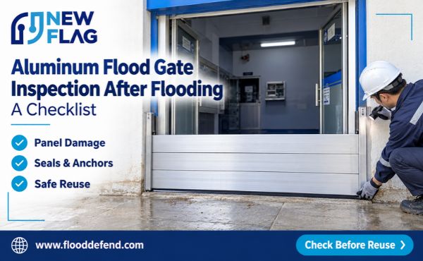
At handover, identify signs that require investigation: frame movement, cracking around fixings, missing fasteners, displaced base plates, or corrosion affecting components. Operators should report these conditions before relying on the gate.
Renovations can change the structural path. Replacement shopfront frames, new flooring, altered wall openings, or relocated services may affect the approved arrangement. Include the gate in alteration reviews rather than assuming it remains valid indefinitely.
Conclusion
Reliable aluminum flood gate anchoring depends on a continuous load path from the barrier into suitable building structure. Wall finishes, decorative door frames, and floor coverings cannot establish structural capacity. Before installation, confirm the substrate, obtain gate support reactions, and coordinate anchor selection, frame stiffness, edge distances, and sealing details.
Follow the approved fixing instructions, record installation changes, and verify that the assembled gate seats correctly. Keep drawings and fixing records available for future inspections. Any cracking, movement, corrosion, or building alterations should trigger review before deployment, helping preserve both structural support and the intended flood protection of the assembly.