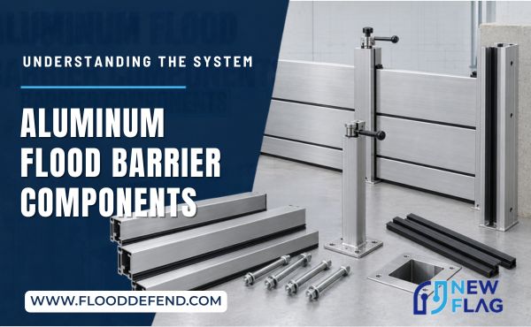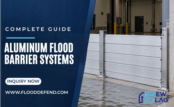
Aluminum flood barriers are complete assemblies, not standalone metal panels. Their main components include stop-log planks or flood panels, wall channels, intermediate posts, seals, compression hardware, anchors, and ground interfaces. Each part either resists and transfers water loads, controls leakage, or allows the barrier to be installed and removed safely.
Understanding these functions helps engineers, contractors, and procurement teams compare systems correctly. Strong planks cannot compensate for weak anchors, and high-quality seals cannot close uneven thresholds. Every component must suit the assembly and supporting structure.
How Aluminum Flood Barrier Components Work Together
Two paths determine performance. The structural load path carries pressure through the planks, channels or posts, anchors, and supporting structure. The sealing path limits water movement between planks and along the sides and bottom.
Water pressure increases with depth. Raising the protection height or widening the span therefore changes forces throughout the assembly. Deeper profiles, shorter spans, more posts, stronger anchors, or improved foundations may be required. Adding stop logs without checking the complete load path is unsafe design practice.
Flood barriers should not be assumed to create completely watertight spaces. Testing normally reports leakage under defined conditions. Seal condition, installation, wall joints, drains, and penetrations affect site performance, so protected areas may still require drainage or pumps.
Main Components of Demountable Aluminum Flood Barriers
| Component | Main Function | What Buyers Should Verify |
|---|---|---|
| Stop-log planks or panels | Form the primary barrier face | Allowable height, span, deflection, and configuration |
| Wall channels or receivers | Support plank ends and transfer reactions | Substrate, anchors, alignment, and seal interface |
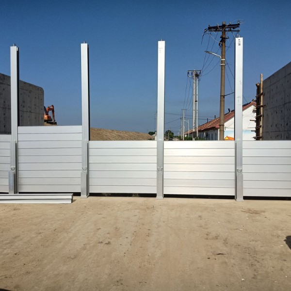
| Intermediate posts | Divide long barriers into engineered spans | Post spacing, base connection, and foundation capacity |
| Horizontal, side, and bottom seals | Control leakage through joints and boundaries | Material, compression, exposure, and replacement method |
| Compression and locking devices | Seat planks and maintain seal pressure | Operation, adjustment, access, and installation sequence |
| Anchors and fasteners | Connect the system to the building or foundation | Type, embedment, edge distance, and corrosion compatibility |
| Ground sockets, rails, or base plates | Locate posts and create the lower support interface | Level tolerance, drainage, traffic loading, and covers |
Quotations may exclude concrete work, wall strengthening, threshold leveling, waterproofing, drainage, or pump power. Procurement documents should separate supplied hardware from site construction.
Aluminum Stop-Log Planks and Flood Panels
Stop-log barriers stack horizontal planks to a specified height. Extruded profiles may incorporate interlocking edges and gasket channels so adjacent planks align and compress together. Their modular format can simplify handling and support different verified configurations.
Flood-panel barriers use larger closures. They reduce horizontal joints but may need more handling space or lifting assistance. Selection depends on opening width, water depth, component weight, storage, crew capacity, and verified limits.
“Aluminum” does not define structural capacity. Confirm the alloy and temper, profile geometry, allowable spans, finish, and connections. Strength depends on the complete section and its supports, not a generic label such as “marine grade.”
Wall Channels, Intermediate Posts, and Ground Connections
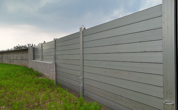
Wall channels, also called receivers, support plank ends and transfer reactions into the building. Their alignment and structural backing are critical. Attaching receivers to cladding or weak masonry without verified support can break the load path even when the planks are adequate.
Intermediate posts divide wide openings or perimeter runs into shorter spans. They transfer loads through base plates, sockets, rails, or foundations. Corner posts change barrier direction, while end posts connect runs to fixed structures.
Each post needs a defined base connection. Sockets require drainage and covers; base plates require verified anchors and level bearing surfaces. Covers in traffic areas must carry expected loads. Along long runs, alignment errors can interfere with plank installation and seal compression.
Seals and Compression Hardware
Horizontal gaskets limit leakage between planks, side seals close interfaces with channels or posts, and bottom seals follow the threshold or rail. Performance depends on compatible materials, correct compression, clean surfaces, and acceptable tolerances.
Top clamps, screws, wedges, or locks compress the seals. Excessive or uneven force can damage gaskets; insufficient force leaves leakage paths. Instructions should define component order and locking procedures.
Check seal materials against temperature, ultraviolet exposure, saltwater, chemicals, oils, and storage conditions. Inspect gaskets for cuts, permanent deformation, contamination, or lost elasticity. Replacements must match the specified profile and material.
Anchors, Fasteners, and the Supporting Structure
Anchors connect channels, posts, and rails to walls, slabs, or foundations. Performance depends on type, embedment, spacing, edge distance, substrate strength, and installation. Fasteners must be compatible with aluminum and the environment to limit galvanic corrosion.
For retrofits, concrete strength, reinforcement, slab depth, masonry, waterproofing, and concealed services may restrict anchors. Survey these conditions before fabrication because relocating channels or posts changes dimensions and spans.
Calculations should match the offered height, width, post spacing, supports, anchors, and substrate. Evidence for one arrangement should not be applied automatically to taller, wider, or differently supported installations.
Components That Support Deployment and Maintenance
A workable system also needs correctly designed support items. These may not resist water directly, but missing or damaged items can prevent timely deployment:
- labeled storage racks, lifting handles, transport carts, socket covers, installation tools, spare seals, and configuration drawings;
- drainage channels, sumps, pumps, alarms, or backup power where leakage, rainfall, or seepage must be managed.
Component labels should match the opening or barrier segment shown on the deployment drawing. Storage must protect sealing surfaces and keep the system accessible above the anticipated flood level. A timed trial assembly should confirm that the intended crew can identify, transport, install, lock, and inspect every component within the available warning period.
Conclusion
Reliable aluminum flood barriers depend on coordinated components, not on planks alone. The barrier face, channels, posts, seals, compression devices, anchors, and foundations must create continuous structural and sealing paths. By checking each component against the proposed height, span, substrate, exposure, and deployment plan, buyers can identify incomplete quotations and avoid weak interfaces that are easy to miss during product comparison.