
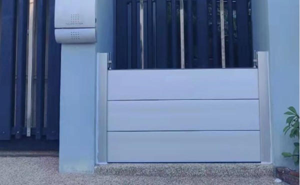
Aluminum flood gates for doorways must fit the opening where the barrier will seal, rather than simply match the width of the door leaf. A useful survey records the clear opening at several heights, the available mounting surfaces, the threshold profile, and the space needed to position and compress the gate. Those measurements allow the supplier to establish the manufactured dimensions and installation allowances.
For building owners, contractors, and procurement teams, the main risk is ordering from an incomplete measurement. A panel can cover the doorway visually while leaving unsuitable seal contact surfaces or inadequate room for its mounting frame. The following approach turns a basic doorway measurement into information that supports a workable fit.
The Barrier Location and Measurement Reference
First decide where the flood gate is intended to sit. An opening-mounted gate seals within the reveal, while a face-mounted arrangement spans the opening and attaches to surfaces beside it. These arrangements need different measurements. Neither should be selected from appearance alone: the available structure, seal contact area, door movement, and water-facing direction all matter.
Mark the proposed barrier line on a photograph and a simple plan. Include the exterior side, interior side, and direction from which water is expected. This prevents the supplier from interpreting an outside wall measurement as an internal reveal measurement.
Identify the reference surfaces clearly. A measurement between decorative trim is different from one between structural walls. Likewise, the distance between existing door jambs may be irrelevant if the gate frame will attach outside them. Describe what each dimension measures rather than sending an unlabeled list of numbers.
Measure the finished condition whenever possible. If cladding, rendering, flooring, or a new sill will be added, show the proposed finishes separately. An opening measured before renovation may change enough to affect seal compression or frame position.
Opening Width, Shape, and Available Height
Record the width at the bottom, midway up the proposed barrier height, and near its top. Add measurements wherever the reveal changes shape. These readings show whether the opening narrows, widens, or contains a local projection. Do not average them into a single ordering dimension.
Check the vertical sides for plumb and record the diagonals of the proposed mounting rectangle. Diagonal differences can indicate an opening that is out of square, but equal diagonals alone do not establish that every surface is straight. A straightedge helps identify bowed or irregular jambs that a tape measure can miss.
Provide the usable height of each side mounting area, not just the door opening height. Handles, glazing beads, conduits, and wall fittings may interrupt the gate frame at the intended protection level. A supplier needs to know whether its complete frame and adjustment hardware can fit.
Distinguish three height values:
- The surveyed elevation of the threshold or seal contact line.
- The required flood protection level established for the site.
- The physical height of the proposed gate and its frame.
A physical panel height is not automatically the rated water depth. Keep these values separate so the design team can assess the selected configuration without confusing site elevations and product dimensions.
Mounting Faces and Reveal Depth
Measure the usable mounting width on both sides of the opening. For a face-mounted gate, this is the uninterrupted area available beside the doorway. For an opening-mounted arrangement, record the reveal depth and any change in that depth along the sides.
Photograph the surfaces closely enough to show joints, cracks, and finish materials. A smooth painted cover may conceal a hollow section or weak backing. Measuring the visible face establishes geometry; it does not establish anchoring capacity.
Note nearby corners and edges. A mounting face can be wide enough for a frame while leaving insufficient room for the designed anchor arrangement. Anchor edge distances and embedment requirements must come from the approved fixing design, not an assumed allowance added to the doorway width.
Also check access for installation tools. A narrow recess beside a pipe may allow the frame to fit but prevent drilling, tightening, or later inspection. Record these obstructions before the manufacturer positions its fixings.
For pressure-fit products, the reveal must provide the support and contact geometry specified for that particular model. Do not treat pressure fitting as a universal way to avoid structural assessment. The reaction forces still enter the surrounding opening.
Threshold Profile and Seal Contact
Survey the threshold across the actual bottom sealing line. Record slope, steps, raised door sills, recessed tracks, tile joints, and drainage channels. A floor that appears level from a standing position can contain a small local depression that interrupts gasket contact.
Use a straightedge to identify gaps and show their locations on the survey. Measure changes in elevation against one stated reference. The supplier can then assess the profile against the bottom seal’s approved working range. Avoid specifying a generic flatness tolerance before a product has been selected.
The bottom seal needs a continuous contact path. A drainage groove crossing that path is not the same problem as a broad, gentle slope. The groove may form a direct water route even when the surrounding floor is flat. Show both its width and depth, and explain whether it connects to an exterior drain.
Do not assume a thicker gasket will solve every irregularity. Additional rubber can change closure force, side seal alignment, and the geometry at the bottom corners. Ground preparation or a designed sill detail may be needed instead.
Keep weather drainage in the survey. A permanent sealing strip or sill modification should not obstruct routine drainage without an approved alternative. The doorway must work during ordinary rainfall as well as when the flood gate is deployed.
Door Movement and Deployment Clearance
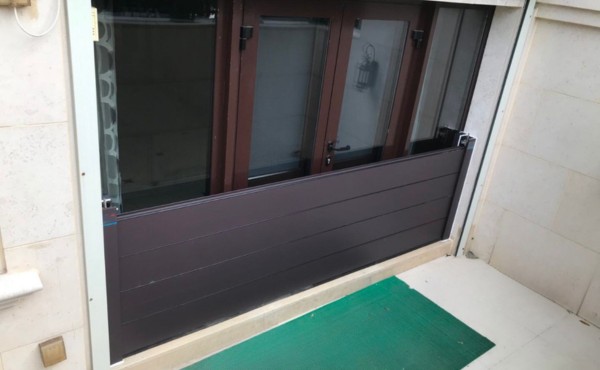
Check the door in its open and closed positions. Show its swing direction, projecting handles, closer arms, and any outward-projecting threshold. A gate installed outside an outward-opening door may prevent the door from opening once protection is in place.
Measure the space required to bring the panel into position. A whole removable panel may need room to tilt, lift, or approach the frame squarely. A narrow corridor can make this difficult even if the gate fits the opening itself.
Hardware clearance deserves a separate check. Operators must be able to reach the latches or compression devices from the intended working side. Do not borrow tool clearance dimensions from another manufacturer’s gate: hardware arrangements differ.
Consider the transport route from storage. Include stairs, tight turns, low ceilings, and changes in floor level. For larger doorway flood gates, handling geometry can determine whether a one-piece panel is practical or a different configuration is necessary.
Finally, review access during deployment. The installed gate changes the doorway’s function. Its location and operating sequence should be consistent with the building’s evacuation arrangements rather than relying on people stepping over the panel.
Survey Records and Supplier Approval
A concise survey pack is more useful than a photograph with one width dimension. Include an opening identifier, a marked plan, dimensioned elevations, threshold details, mounting material information, and photographs with recognizable reference points.
| Survey item | Information to record | Decision it supports |
|---|---|---|
| Opening geometry | Widths at several heights and side alignment | Frame position and fit allowances |
| Mounting area | Usable faces, depth, edges, and obstructions | Mounting arrangement |
| Threshold | Elevation profile and crossing joints | Bottom sealing detail |
| Door operation | Swing and hardware projections | Deployment location |
| Handling route | Turns, stairs, and access restrictions | Panel format and lifting plan |
Ask the supplier to return a drawing showing the measurement references it has used. Confirm the proposed gate line, frame dimensions, seal contact surfaces, and responsibility for any site preparation before fabrication.
For repeated openings, do not assume one survey applies to all doors. Assign each opening its own record, even where architectural drawings show identical sizes. Small differences in finished floors or jamb positions can affect installation.
Conclusion
Reliable measuring for flood gates starts with the sealing location and ends with an approved fit drawing. Record the opening’s shape, structural mounting area, threshold, door movement, and handling space as connected conditions. That information gives the supplier a basis for selecting a workable doorway arrangement and resolving site changes before the gate is manufactured.