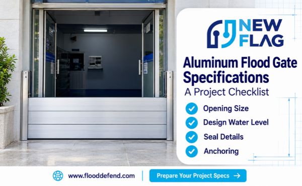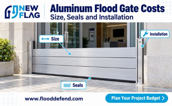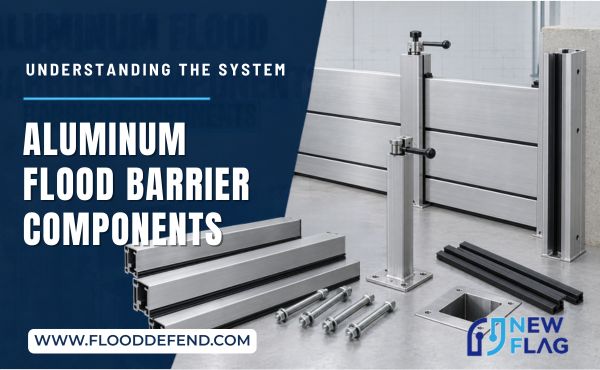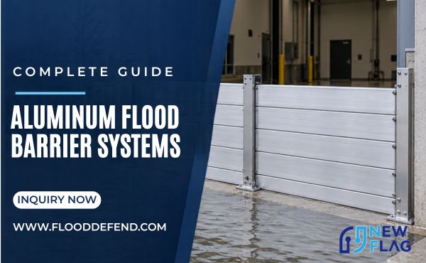
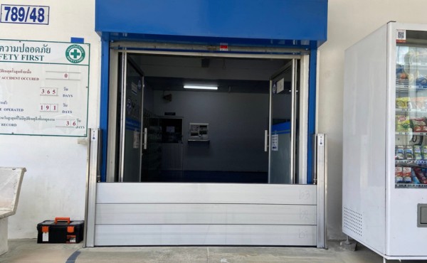
Aluminum flood gate specifications should define the opening, required water performance, supporting structure, sealing conditions, and deployment process. Stating only “custom aluminum flood gate” and a width leaves important design decisions unresolved. A useful project brief gives the supplier enough information to propose a complete assembly and makes acceptance requirements clear to the buyer.
For architects, contractors, and procurement teams, the checklist below separates site inputs from supplier commitments. It is a specification framework, not a substitute for the project engineer’s design or the selected manufacturer’s installation instructions.
Opening Identity and Survey Information
Assign an identifier to each protected opening. Use it consistently on drawings, panel labels, storage locations, and handover records. This prevents an otherwise suitable panel from being delivered or deployed at the wrong entrance.
Record the proposed barrier line and mounting arrangement. Show the water-facing side, interior side, and measurement references. Include widths at several heights, usable mounting faces, reveal depth, threshold profile, and obstructions.
Provide photographs that explain the geometry rather than replace it. A front view, views of both mounting areas, and a close view of the floor contact line help the supplier interpret the dimensioned survey. Note concealed construction that remains unverified.
For new construction, state whether dimensions are design values or verified finished measurements. Identify any finishes still to be installed. Agree who performs the final measurement check before fabrication and what happens if the opening changes.
Double doors and wide entrances need the complete span, existing mullion details, and space for any center support. Do not specify only the individual door leaf dimensions.
Water Level and Exposure Requirements
Define the required protection level against an identified elevation reference. State the threshold elevation and corresponding design water depth at the gate. Avoid mixing a site flood elevation with a height measured from the finished floor.
Identify whether the protected side is assumed dry and which direction the water acts. Some systems are designed for one water direction; reverse loading or internal retention may need a different assessment.
Describe the relevant exposure conditions, including duration where established, moving water, waves, and debris. Where information is uncertain, flag it for the responsible designer instead of assigning an unsupported rating.
Specify the accepted leakage criterion and the basis on which it will be assessed. “Fully waterproof” is difficult to evaluate without a defined test and limit. If residual water management is required, assign its design separately.
Overtopping and full submergence are different conditions. A barrier with three-sided sealing is not automatically suitable for an opening that can become submerged. State whether a top sealing connection or another protection strategy is required.
Structural Supports and Building Interfaces
Describe the actual substrate at each fixing location. Include material, thickness where known, condition, and relevant concealed details. Distinguish structural concrete or masonry from render, cladding, screed, and decorative frames.
Require the supplier to identify support reactions for the proposed configuration and clarify responsibility for anchorage design. The contractor needs an approved fixing arrangement, not permission to select bolts from the appearance of the frame.
For center posts or braces, define the receiving floor or foundation and space available for its connection. State whether removable sockets, permanent base plates, or another detail is acceptable in normal use.
Specify how the frame-to-building interface will resist water bypass. Coordinate that detail with wall finishes, floor joints, and the bottom corners. Assign responsibility for substrate preparation and interface sealing.
Where the existing structure is unsuitable or unknown, include investigation and enabling works in the project scope. Do not leave a structural assumption unresolved until installation day.
Assembly, Materials, and Seal Details
State the proposed gate format: whole removable panel, divided gate, stackable system, or permanently attached closure. The supplier should explain the component arrangement rather than use a broad product label that obscures the design.
Request the panel and frame material specifications, finish, connection details, and approved fasteners. Material identification supports traceability, but it should not replace performance requirements for the complete assembly.
For seals, require the approved profile, installation position, retention method, and replacement identification. If exposure to oils or chemicals is credible, ask for compatibility confirmation for the actual compound.
Define the closure or compression method and how operators verify the correct condition. Where torque or adjustment limits apply, they should appear in the product instructions. Avoid writing generic compression values into the project specification.
If panels meet at a center connection, request the joint and bottom intersection drawings. These details determine how the complete sealing path remains continuous and how the assembly sequence works.
Deployment and Normal Access Conditions
State who will operate the gate, their expected availability, and the warning conditions used by the site. Give realistic constraints such as after-hours access, multiple entrances, or the absence of mechanical lifting equipment.
Require the largest component dimensions and weights. Weight alone does not establish handling practicality: the panel must pass through the storage route and be positioned at the opening. Include turns, stairs, and restricted working areas.
Specify the storage arrangement and required tools. Identify who supplies racks, covers, lifting aids, and labels. Operators should not need to improvise protection for the seals or search for a proprietary tool during an alert.
Review permanent fittings against everyday access. Rails, floor plates, sockets, and parked hinged panels can affect pedestrian routes, trolleys, and door operation. Coordinate accessibility and evacuation requirements with the responsible building professionals.
The project should include the full deployment sequence, final checks, and safe removal conditions. Avoid accepting an advertised installation time as proof that the site’s response plan is adequate.
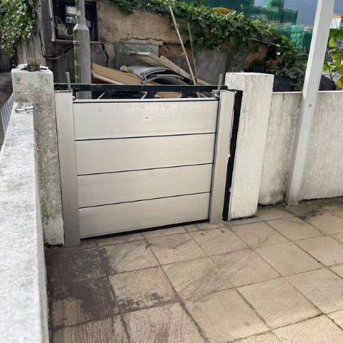
Evidence, Acceptance, and Handover
Ask for performance evidence applicable to the supplied configuration. Identify the product, dimensions, mounting arrangement, test conditions, and limits represented by the evidence. A brochure logo or a report for another model is insufficient to establish applicability.
| Specification item | Required project response |
|---|---|
| Dimensions | Approved drawing tied to the surveyed opening |
| Water requirement | Protection level, depth, direction, and exposure scope |
| Structure | Support reactions and assigned anchorage design |
| Sealing | Threshold, corners, joints, and building interfaces |
| Operation | Operators, tools, handling route, and storage |
| Acceptance | Defined checks, any agreed tests, and pass criteria |
| Handover | Instructions, parts identification, records, and training |
Define field acceptance before installation. A dry assembly can check seating and operation, while any water test requires a controlled procedure and stated criteria. Do not require an improvised on-site flooding exercise without a safe, agreed test arrangement.
Handover should include the approved final drawings, installation records, operating instructions, maintenance guidance, spare part references, and training records. Record changes made during construction so the documentation matches the installed system.
Responsibility and Change Control
Assign responsibility for survey accuracy, gate design, structural assessment, site preparation, installation, and acceptance. These roles can be shared, but each decision needs an owner. Otherwise a supplier may assume the floor is ready while the contractor assumes the gasket compensates for it.
Require approval before substituting panels, seals, fixings, or sill details. Even a seemingly minor substitution can change fit, compression, or load transfer. Track the final accepted configuration rather than retaining only the original tender description.
Include future alteration checks. New flooring, replaced door frames, moved storage, or changed staffing can affect the protection arrangement. The gate’s specification should remain connected to its actual operating conditions throughout service.
Conclusion
Good flood gate technical specifications connect the site survey to measurable performance, structural support, sealing, and operation. Use the checklist to expose missing inputs and assign responsibility before manufacture. The resulting approval and handover records should describe a complete protection arrangement that the site can install, operate, inspect, and maintain.