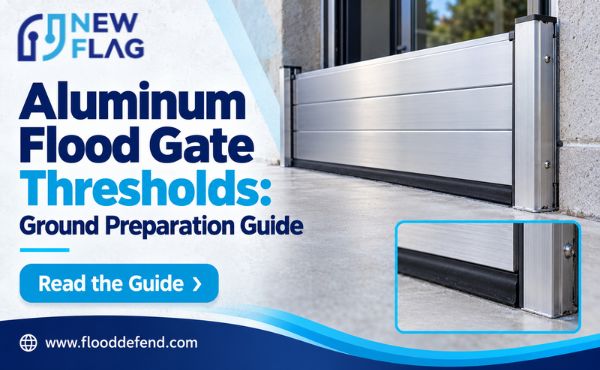
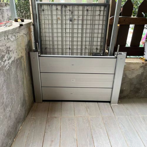
Aluminum flood gates can leak through an under-compressed or damaged seal, an uneven threshold, a misaligned panel joint, or an unsealed mounting interface. Water may also bypass the gate through adjacent walls, drains, or penetrations. The useful first step is to locate the entry route rather than immediately tighten every clamp or replace every gasket.
For contractors and building maintenance teams, troubleshooting should separate the symptom, the likely mechanism, and the corrective action. Bottom leakage does not always mean a defective bottom seal, and a wet patch near a frame does not prove water crossed the panel-to-frame contact.
Leakage Location and Event Records
Record where water first appears, its approximate flow pattern, and the water level at that time. Photographs taken from a safe location can help distinguish a concentrated stream from scattered seepage. Note whether the leakage began immediately or increased as the external level rose.
Identify the gate configuration, opening, installation team, and deployment sequence. Record any difficulty seating the panel, missing hardware, last-minute adjustments, or material trapped beneath the seal. These observations often narrow the investigation more effectively than the amount of water alone.
Compare the event with the rated conditions. Water above the protection level, unassessed impact, or exposure outside the design scope can produce problems that seal replacement will not correct. Keep evidence of unusual conditions for the supplier’s review.
Leakage should be assessed against the product’s specified acceptance criteria. A marketing phrase such as “watertight” does not define a measurable leakage limit. Obtain the relevant performance documentation rather than assuming every visible drop establishes a manufacturing failure.
Do not dismantle or loosen a loaded gate to inspect it. Investigate the assembly after water levels and pressure permit safe access and removal. During an event, follow the site’s flood response plan and avoid placing operators at a retained-water barrier.
Leakage Along the Bottom Seal
A local stream beneath one point often suggests an interrupted contact line. Common causes include grit, a floor depression, an open tile joint, a threshold groove, or a damaged gasket corner. Mark the location before removing the panel so it can be matched to the corresponding surface.
After safe removal, clean and inspect both the gasket and floor. Look for an imprint from trapped debris, cuts in the rubber, or a contact pattern that changes sharply at the leak location. Check whether the gate seal sat on the intended line or accidentally bridged a recessed track.
Broad leakage across the bottom can indicate insufficient compression, a panel that did not seat fully, or an incompatible threshold profile. Confirm the supplied bottom component and its orientation. In a stackable system, using the wrong section at the base can change the intended floor seal.
The corrective action depends on the mechanism. Remove contamination, replace damaged approved seals, or restore the threshold detail as appropriate. If the contact surface lies outside the seal’s allowable profile, request a designed ground or sill modification.
Avoid solving a floor defect with uncontrolled tightening. Excessive force can overload hardware or distort the assembly without closing a narrow groove that crosses the sealing line.
Leakage at Side Frames and Bottom Corners
Water along a side frame may cross the operational gasket, pass behind the permanent frame, or emerge from the adjacent wall. Inspect these paths separately. Replacing the panel gasket will not seal a failed frame-to-wall interface.
Check that the panel sits at the correct depth and contacts both side seals. A skewed panel can compress one side while leaving the other outside its working position. Confirm the frame alignment against the approved installation drawing.
At bottom corners, examine how the side and floor seals meet. Dirt, a torn corner, an incorrect splice, or a raised frame foot can interrupt the junction. A small defect here can produce a concentrated leak despite apparently sound straight seal lengths.
Inspect permanent interface seals or bedding details for gaps and loss of adhesion. The repair should use the approved material and preparation method. Smearing an unspecified sealant over the visible exterior edge may conceal rather than repair the actual route.
If the mounting frame has moved, investigate its support and fixings. Do not treat a loose or displaced frame as merely a gasket problem. Structural movement may change the sealing geometry and require engineering review before the gate returns to service.
Leakage Through Panel Joints
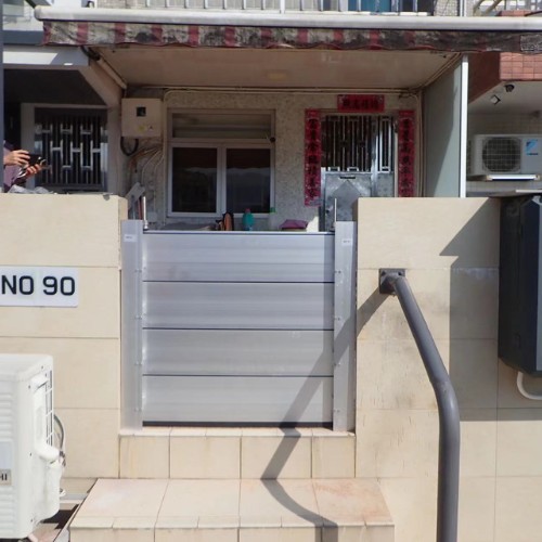
Divided gates and stop-log systems introduce joints absent from a one-piece panel. Check that the components belong to the same opening, are in the specified order, and face the correct direction. Similar sections can have different bottom, top, or joint details.
Inspect the mating surfaces for dirt and damage. Confirm that the joint reaches its designed position before the compression devices are engaged. A panel resting against an obstruction can leave a gap even when its hardware feels tight.
Where a removable center post is used, check its location and seating. A post installed out of line can affect both adjoining sections. Examine the base connection and the intersection with the bottom seals, where several paths converge.
The correct remedy may involve reassembly, adjustment, gasket replacement, or repair of a support detail. It should not automatically involve adding a strip of rubber to the joint. Additional material can prevent engagement of the designed connection.
A leak appearing only at higher water levels may involve movement under load. Preserve the evidence and ask the supplier to assess panel, joint, and support behavior. A dry fit check alone may not explain that condition.
Water Bypassing the Gate
Before attributing interior water to the gate, inspect other routes. Drains can back up, wall cracks can admit water, and penetrations beside the entrance can remain unprotected. Groundwater may also enter below the floor.
Trace the earliest wet location and compare it with the barrier position. Water emerging behind a wall or through a floor drain points to a different investigation from a visible stream crossing the gasket contact line.
| Leakage pattern | First investigation | Likely repair category |
|---|---|---|
| Local stream at floor contact | Debris, groove, or damaged seal | Cleaning, approved seal, or threshold work |
| Water behind fixed frame | Frame-to-building interface | Interface repair |
| Flow at center connection | Component order and post seating | Joint or support correction |
| Wet floor away from gate | Drain, penetration, or groundwater | Building protection or drainage work |
| Increasing leakage with visible movement | Frame, panel, and anchoring | Structural assessment |
The table is a diagnostic starting point, not proof of a single cause. More than one route can operate during the same event. Repair records should identify which route was confirmed and how it was addressed.
Corrective Work and Return to Service
Create a repair plan based on the identified cause. Use approved parts and adjustment instructions. Record any changes to the floor, frames, fixings, or seal configuration so the installed condition remains traceable.
Perform a dry assembly after repairs. Check seating, hardware operation, seal continuity, and access to all compression points. Parts should align without improvised packing or excessive force.
Where a water test is required, agree the procedure and acceptance criteria with the manufacturer and project team. Uncontrolled flooding of the entrance can damage the building or expose people to loads the temporary test arrangement cannot safely contain.
Document the result and update deployment instructions where the event exposed an operating error. A technical repair is incomplete if the same component mix-up or cleaning omission remains likely at the next deployment.
Conclusion
Practical flood gate leakage repairs begin with the actual water route. Investigate bottom contact, side interfaces, joints, and bypass paths separately, then apply a correction that restores the approved assembly. Record the event, verify repairs under an agreed procedure, and resolve deployment errors before relying on the gate again.